An Introduction to the Newest Generation of Scientific Camera Cooling Technologies
Overview
Many low-light imaging and spectroscopy applications rely on highly sensitive silicon- or InGaAs-based scientific detectors. These applications, which include astronomical photometry, in vivo small-animal imaging, Raman spectroscopy, chemi/bioluminescence, and soft x-ray imaging, require deep-cooled cameras that minimize thermally generated dark noise in order to allow integration times ranging from several minutes to multiple hours.
Although a number of cooling technologies (e.g., thermoelectric, cryogenic, Joule-Thomson) have been used in scientific cameras over the years, thermoelectric or Peltier cooling has proven to be the most attractive owing to its maintenance-free and reliable operation. It should also be noted that applications with extremely low light, such as NIR spectroscopy, may benefit from the use of liquid-nitrogen–based cryogenic cooling technologies that chill the sensor beyond -100°C and deliver the lowest levels of dark noise achievable.
The Need for Cooling
Ideally, photonic detectors should provide a signal-to-noise ratio (SNR) that is limited only by photon shot noise. In practice, however, the SNR is lowered by other noise sources, most commonly read noise and dark noise. Mathematically, this is shown in the equations below.
Signal-to-Noise Ratio (SNR) = S/σ, where
S = Detected number of photons
σ = Total Noise = √(σS2 + σD2 + σR2 )
σS = Photon shot noise
σD = Thermal or dark noise
σR = Read noise
Photon shot noise (σS), which is attributable to the stochastic nature of photon arrival rates, is equal to the square root of the number of photons detected. Read noise (σR) is determined by the design of the sensor’s readout electronics and the speed of readout. Dark noise (σD) — the square root of the dark charge, which is typically specified as electrons per pixel per second (e-/p/s) — arises from unwanted signal generated in the sensor’s pixels due to thermal excitation. In a typical silicon-based CCD, dark charge is reduced by half for every 5 to 7 degrees of cooling within the normal operating range. For deep-cooled CCD cameras, a typical dark charge specification of 0.001 e-/p/s at a sensor temperature of -70°C (or colder) is not uncommon
The Fundamentals of TE Coolers
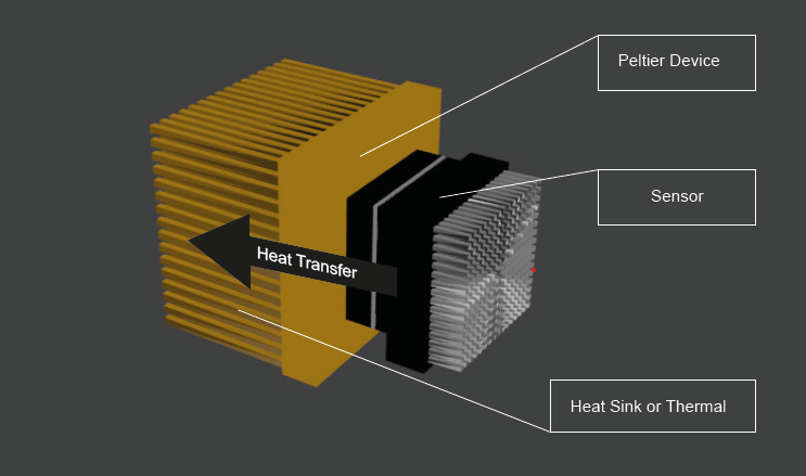
A thermoelectric cooler (TEC) is a solid-state device that transfers heat from one end to the other when electrical energy is applied. This effect is also called the Peltier effect; thus, TECs are referred to as Peltier devices. While the actual materials and architectures used in individual TEC designs are often proprietary, typical materials include bismuth telluride, silicon-germanium, and various bismuth antimony alloys. Although Peltier devices can heat or cool depending on the direction of electrical energy, their most common use is for cooling (see Figure 1). Typically, Peltier devices are rated according to the amount of heat they can transfer

Whereas using a Peltier device to achieve moderate cooling is a relatively straightforward proposition, achieving the deepest cooling with the utmost reliability is not. Often, camera manufacturers refer to using multi-stage (i.e., three-, four-, or five-stage Peltier devices) simply to imply various levels of deep cooling. And though these specifications could theoretically be achieved by their cameras under perfect conditions, such specifications are not necessarily realistic. The entire thermal design, including the Peltier geometry, the sensor thermal load, the input voltage-current (power) parameters, the heat exchanger, and the vacuum chamber design, must be optimized to ensure reliable, deep cooling of the sensor. When done well, cameras with TECs can be specified in terms of the absolute temperature achievable with a degree of headroom to handle reasonable variations expected under various ambient conditions. The newest deep-cooled cameras make use of advanced computational fluid dynamics (CFD) analysis tools to optimize every aspect of thermal design.
Achieving the deepest cooling using TEC or Peltier devices requires
- • Ultrahigh vacuum (UHV) environment around the sensor
- • Non-outgassing materials; no epoxies
- • Permanent, all-metal, hermetic seals
- • Efficient heat exchanger for high thermal dissipation
- • Intelligent controls to achieve high reliability and temperature stability
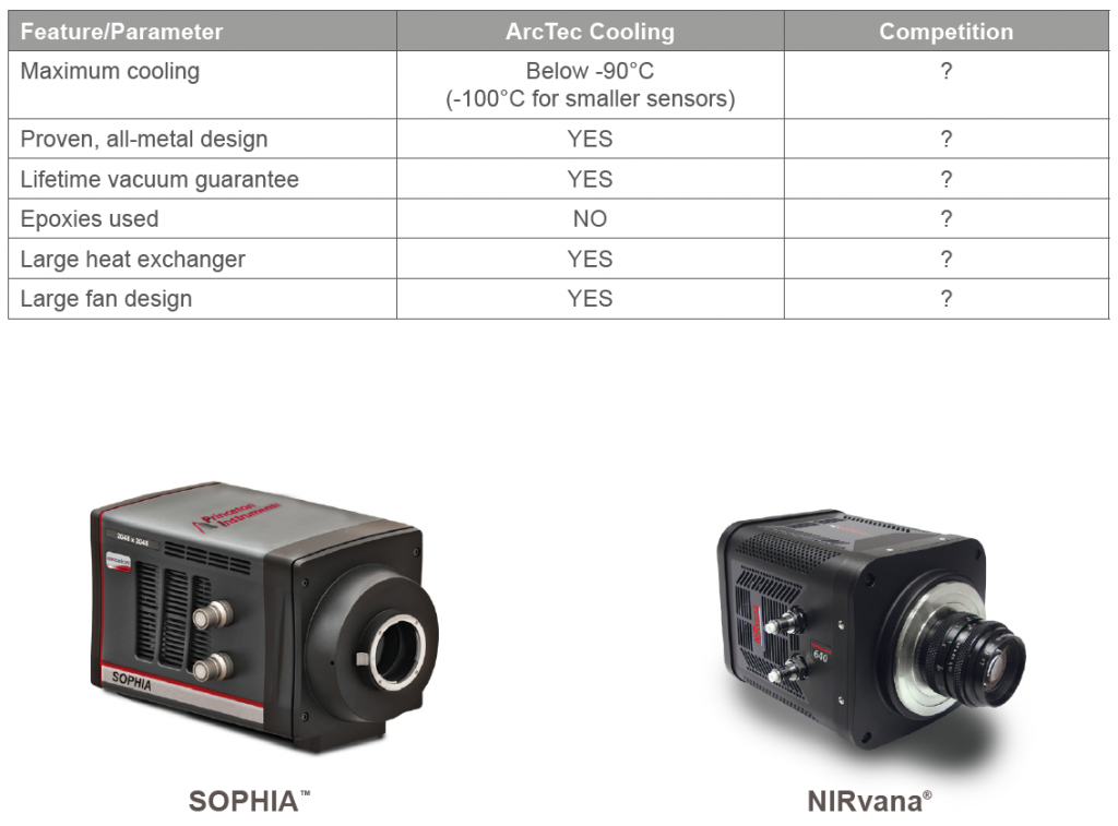
Ultrahigh vacuum: TECs are rated according to the maximum temperature delta achievable between their hot and cold sides, often with ‘zero’ load. However, a TEC not only needs to remove the heat generated by its own operation, it also needs to remove the excess heat generated by the operation of the sensor. In order to keep the thermal load to a minimum, the sensor needs to be encased in an ultrahigh vacuum (UHV) chamber with vacuum levels as high as 10-10 torr. While many UHV chamber designs are available for vacuum chamber construction, only the truly reliable ones are able to guarantee lifetime performance based on years of manufacturing expertise and materials know-how. See Figure 2.

A high-performance vacuum design must have the following attributes:
• An all-metal, hermetically sealed vacuum chamber
• Permanent seals for maintenance-free operation
• No use of epoxies to seal the window and vacuum chamber: epoxies outgas and degrade, inherently compromising the vacuum over time.
• Ultrahigh vacuum levels in the range of 10-10 torr to minimize thermal losses
• Advanced ‘getter’ materials to maintain vacuum levels over many years of operation
• Reliable, proven manufacturing processes
Efficient heat exchanger: Peltier devices provide an easy way to transfer heat from the cold side (sensor) to the hot side (ambient environment), but they are very inefficient. The more heat they transfer, the less efficient they become. In other words, there is an optimal range in which TECs operate most efficiently.
Therefore, it is important for cameras to have heat exchangers, commonly called heat sinks, to remove heat from the hot side as efficiently as possible. ArcTec technology uses a combination air/liquid heat exchanger that maximizes surface area and dissipates heat
efficiently. The heat transferred to the heat sink is dissipated (to the ambient environment) by using an oversized fan, a room-temperature liquid circulator, chillers, or a combination thereof.
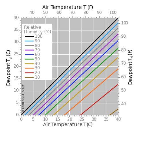
Note: Some manufacturers specify maximum cooling achieved as delta from ambient temperature (ΔT) as opposed to absolute value (T) using chilled liquid as cold as +10°C. However, it is not advisable for laboratories in humid environments or that lack ultra-stable
temperature and humidity controls. Using liquid below the dew point will cause condensation (water vapor accumulation), damaging electronics and sensitive optics surrounding the
cameras. See Figure 3.

Intelligent controls: The latest thermal designs also include intelligent feedback controls that keep the sensor temperature within ±0.01°C of the set point by controlling the electrical parameters of the Peltier device. In addition, such advanced designs either control the speed of the fan (to minimize vibration) or allow the fan to be turned off completely in favor of liquid circulation.
Summary
The latest generation of thermoelectrically cooled scientific-grade cameras offers unprecedented cooling performance and reliability. The new performance levels are achieved by optimizing multiple aspects of the thermal design, including the Peltier geometry, the vacuum chamber, the heat exchanger, and the electronics.
See the Difference: ArcTec™ Cooling Technology
Princeton Instruments SOPHIA cameras, introduced in 2016, utilize ArcTec advanced thermoelectric cooling technology. First pioneered in our NIRvana line of InGaAs focal plane array (FPA) cameras and based on Princeton Instruments’ proven, all-metal, hermetic vacuum design, ArcTec uses the latest computational fluid dynamics (CFD) analysis tools to offer the highest level of cooling and reliability available for any TEC-based cameras on the market today.

